


High-Voltage Motor Windings: Partial Discharge Key Points And Insulation Reliability
Feb 10, 2026
Leave a message
Two Key Factors Causing Partial Discharge in High-Voltage Motor Windings - Limit Voltage and Dangerous Air Gap!
For high-voltage motors, a very dangerous quality hazard is the adverse impact of partial discharge on windings during motor operation. The factors leading to partial discharge in motor windings are voltage and air gap. Then, do all high-voltage motors have partial discharge problems?
It can be known from theoretical calculation and analysis that for motors with a rated voltage greater than 5.5kV, partial discharge may occur inside the winding insulation. The dangerous air gap thickness is 0.1-0.6 millimeters, and partial discharge may occur even at a lower rated voltage.
The actual air gap of high-voltage motors is generally 0.05-0.5 millimeters. Therefore, motors with 6kV and above usually have partial discharge problems during operation. When the rated voltage increases, partial discharge will occur regardless of whether the air gap is thick or thin. When the air gap thickness is less than 0.05mm, motors with a rated voltage of 15kV will also have the risk of internal discharge.
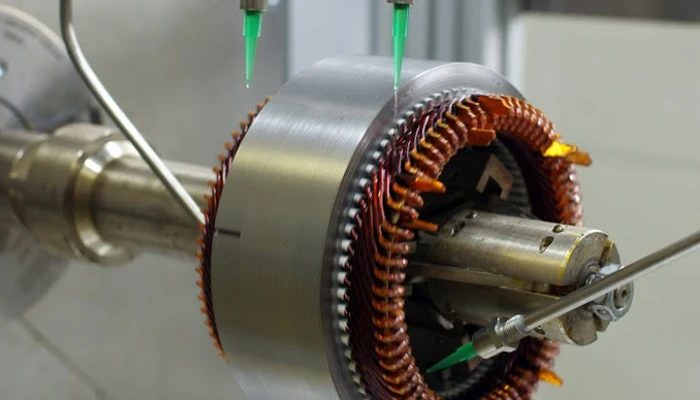
Insulation Structure and Performance Reliability of High-Voltage Motor Stator Windings
From the perspective of the overall insulation structure of high-voltage three-phase AC asynchronous motors, compared with the main insulation, the inter-turn insulation has the characteristics of thin insulation, large contact area; during motor operation, especially during startup, it bears high overvoltage; during coil manufacturing, the inter-turn insulation is subjected to mechanical force during shaping, overheating during pressing, and thermal stress during operation. In particular, the inter-turn insulation of frequency conversion motors also has to bear the high-frequency instantaneous pulse peak voltage output by AC frequency converters. Therefore, the inter-turn insulation structure is one of the key points in the entire insulation structure. Since the inter-turn insulation treatment scheme is related to the motor type, number of coil turns, winding method, voltage level, operating conditions, etc., improper treatment will cause quality hazards.
To ensure the operational reliability of high-voltage motors, the motor windings should have sufficient electrical breakdown strength and corresponding heat resistance grade; the motor windings should be able to withstand various mechanical forces during manufacturing and operation; have good corona resistance performance; and under the condition of not affecting various performances, the thinner the insulation thickness, the better.
● Selection of Magnet Wire
For the inter-turn insulation of magnet wires commonly used in high-voltage motor coils, except for special specifications that need additional insulation wrapping, it is mainly the insulation of the magnet wire itself used in the coil, so the selection of magnet wire is crucial. High-voltage motors are generally Class F motors, and the heat resistance grade of the magnet wire should match that of the motor. From the analysis of processing technology and motor operation reliability, self-adhesive magnet wire is more suitable. In terms of magnet wire selection, thin and flat specifications should be avoided as much as possible, because such magnet wires have many problems in operation and are prone to many inter-turn problems.
● Coil Embedding Process and Insulation Control of the First Coil
When the motor generates overvoltage, it is generally not during normal operation of the motor, but at the moment of startup. The overvoltage is generally a steep wave impulse voltage. Since this instantaneous overvoltage is introduced by the cable lead, it is impossible for the entire winding of the motor to reach the same voltage level at the same time. The first coil connected to the cable bears more than 50% of the overvoltage. Therefore, inter-turn breakdown of the winding mostly occurs in the first coil during startup. The steep wave impulse voltage resistance level of the entire motor should be improved by strengthening the inter-turn insulation of the first coil.